The delivery of housing in Trafford must meet the accessibility standards of M4(2) Category 2: Accessible and adaptable dwellings as a minimum to provide good quality and accessible housing.
Applicants must comply with the Building Regulations accessibility category as stated for all new external and internal areas of homes.
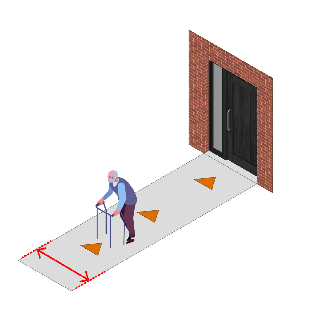
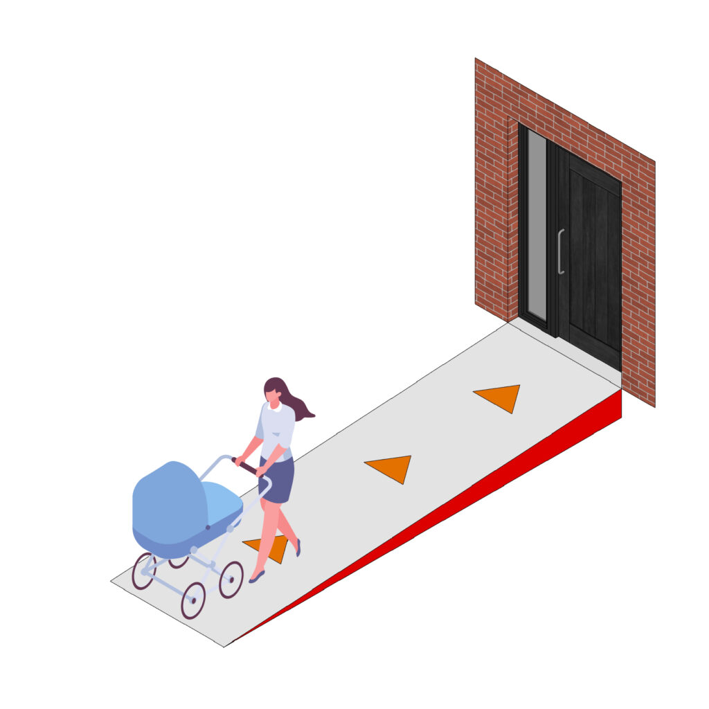
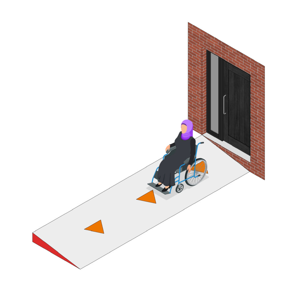
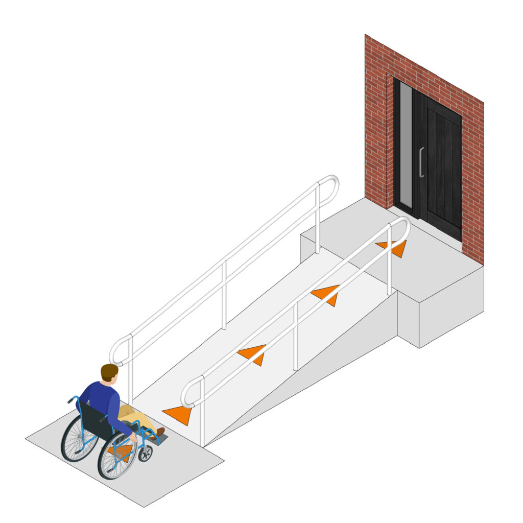
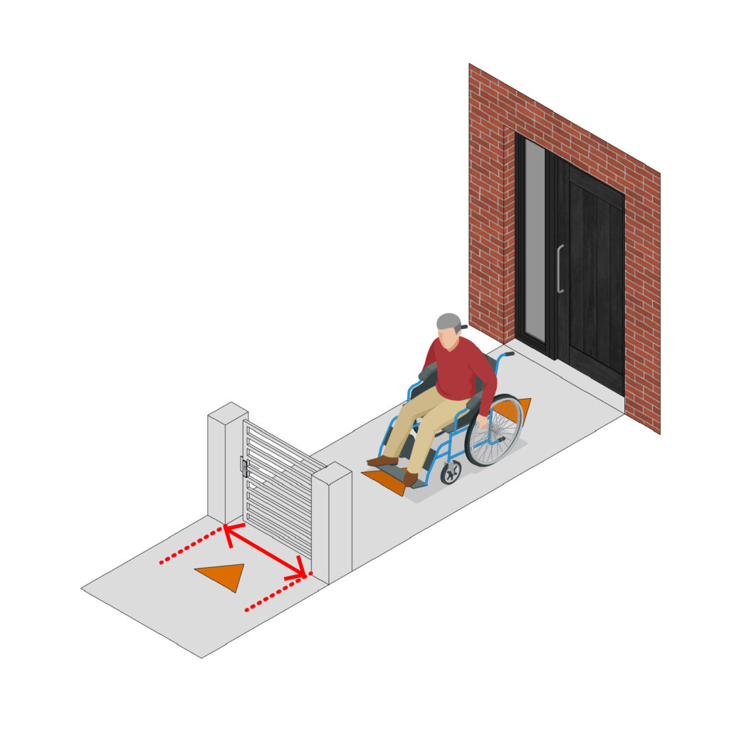
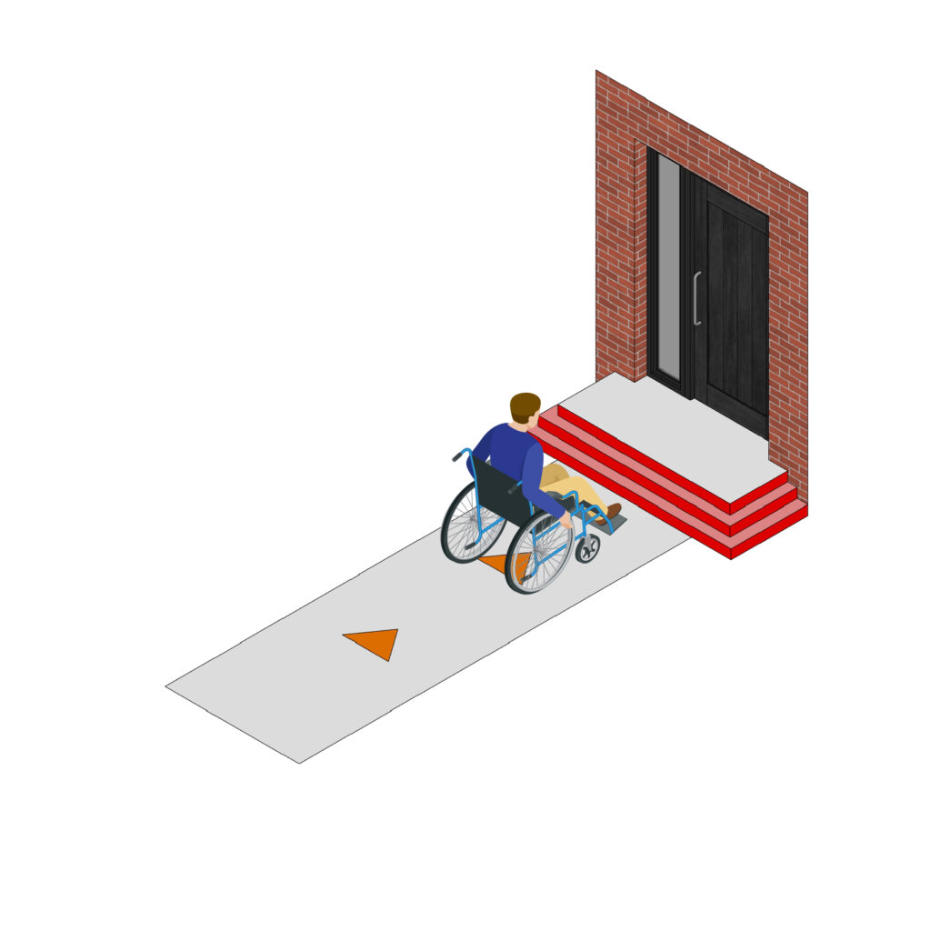
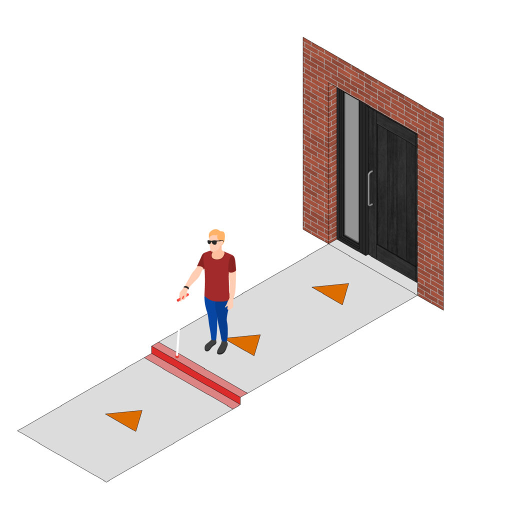
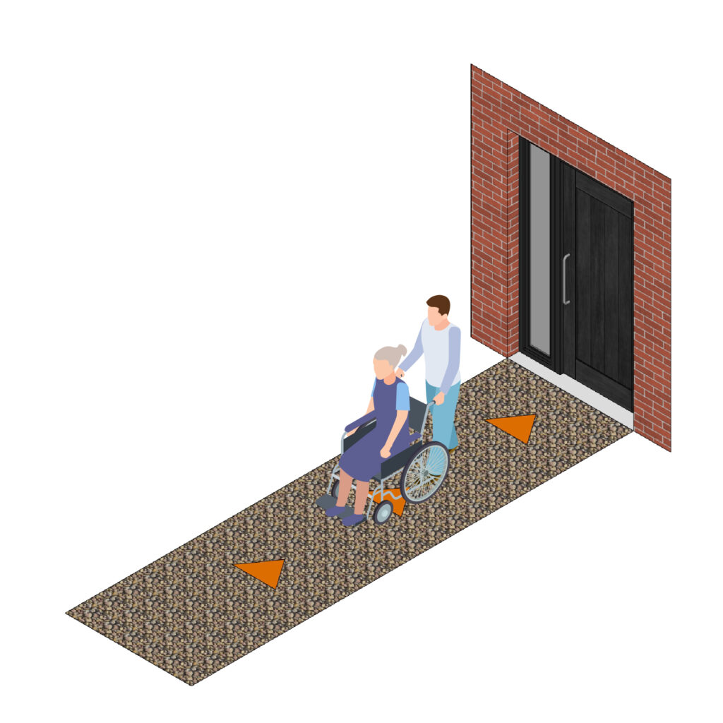
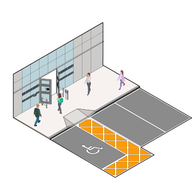
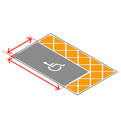
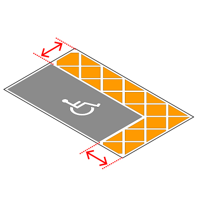
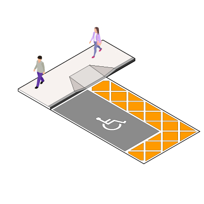
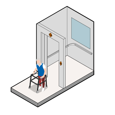
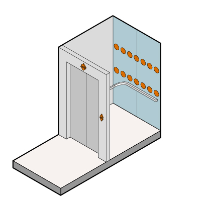
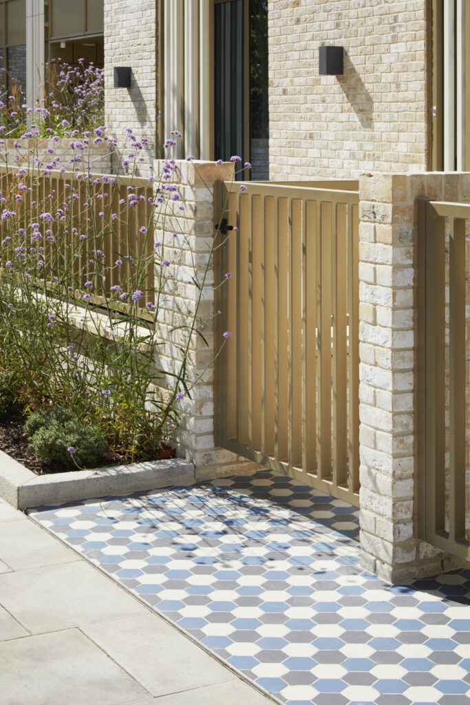
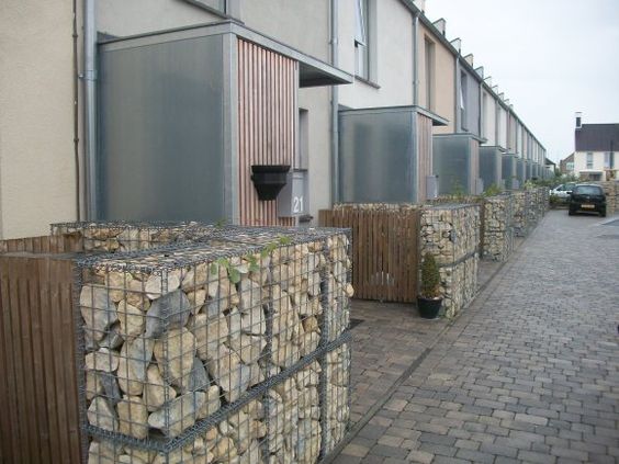
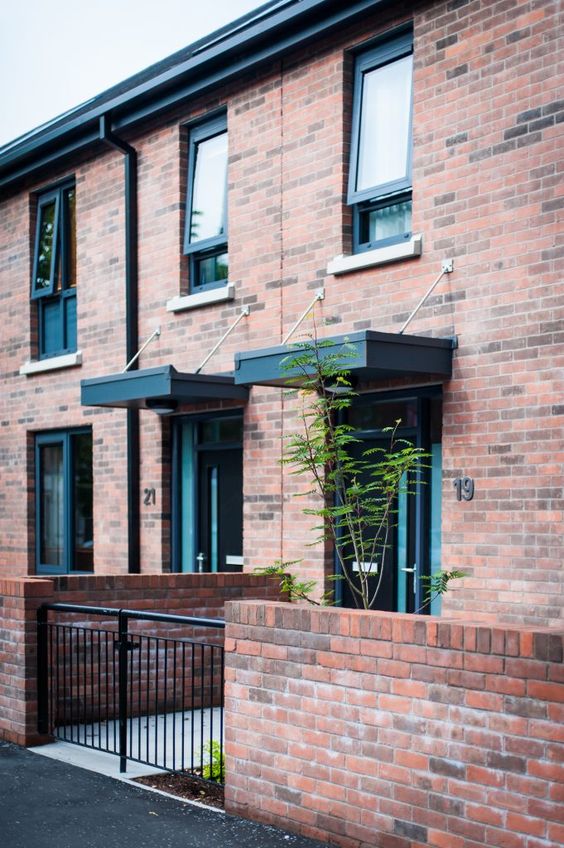
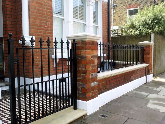
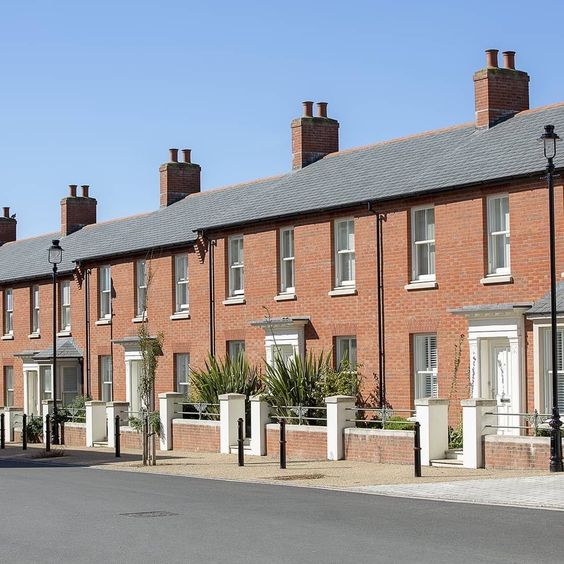
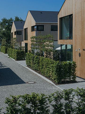
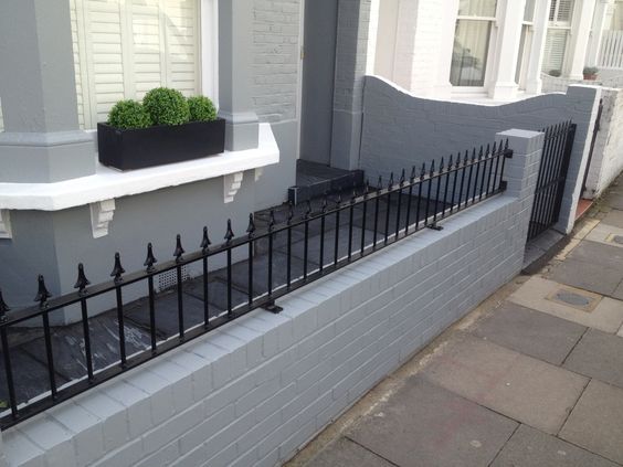
Ensure that site levels are fully considered at all stages of planning. Approaches should be included that are level, step-free and built with firm stable and slip resistant materials.
Best practice design for approaching homes makes homes safe for all users. Mistakes in design and construction phases can make homes unsuitable for inhabitants with current or future mobility issues.
Applicants should demonstrate in their submission how this element of the Code has been complied with.
Documents required:
- M4(2) / M4(3) Compliance Statement
Further guidance: